Table of Contents
Autofunctions App Overview
Top Bar
Press ![]() to open the menu.
to open the menu.
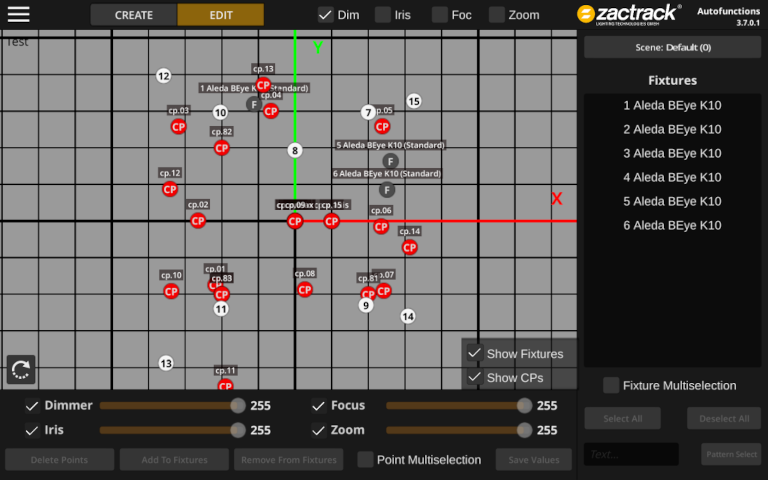
The two buttons CREATE and EDIT can be used to switch between different modes during the creation of autofunction zones.
Use the toggles Dim, Iris, Foc and Zoom to switch between different zone visualization modes.
2D Viewport
The largest portion of the autofunctions tool's user interface is a (2D) view port in the middle of the screen, showing labeled ![]() autofunction and
autofunction and ![]() calibration point as well as
calibration point as well as ![]() fixture positions on a 1×1 meter grid.
fixture positions on a 1×1 meter grid.
The red line represents the x-, the green line the y-axis.
Use the two checkboxes Show Fixtures and Show CPs to toggle the display of calibration point/fixture positions on/off.
Use common pinch & zoom gestures to zoom in/out and use the scrolling gesture to move the camera.
Press the ![]() button to rotate the view by 90 degrees.
button to rotate the view by 90 degrees.
The name of the current show is (subtly) placed in the top left corner.
This part of the screen is also used to create autofunction zones for different fixtures. See Define Autofunction Zones with the Autofunctions App for more information.
Fixture List
The right part of the screen contains a list with all the fixtures of the currently loaded show. Tap on a fixture to select it, which will highlight the corresponding icon in the viewport (if available) and show the autofunction zones defined for that fixture.
Use the toggle Fixture Multiselection and the buttons Select All / Deselect All to (de)select multiple fixtures at once.
Pattern Select can be used to select all fixtures containing the text in the adjacent text field.
The button Scene: xx (x) shows the currently selected scene and can be clicked to manage scenes.
Bottom Bar (Autofunction Point Controls)
The bottom bar contains controls used during autofunction zone creation and is explained in greater detail on the dedicated subpage.
