Measure
All necessary hardware has been setup and powered on in the prior steps, now the showfile needs to be created in order to calibrate the tracking system and integrate other systems later on.
The following procedure summarizes the Measurement step:
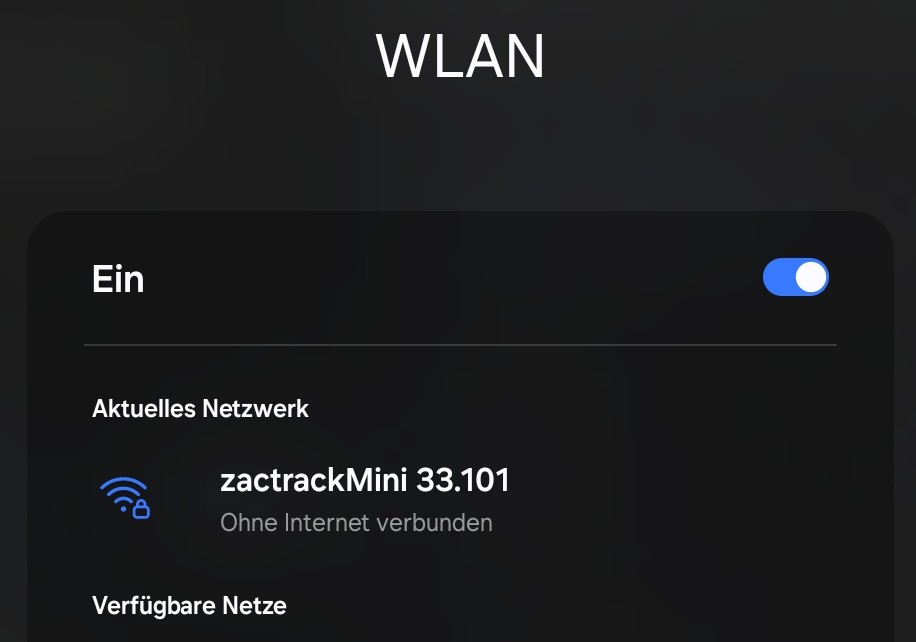
Connect to Wi-Fi
Open the Wi-Fi settings of the tablet.
Connect to the Wi-Fi which the server is providing. The default SSID and passphrase is printed on the label on the server backside.
 |
Note
The WiFi configuration (SSID, passphrase, frequency, channel etc.) can be changed and reset to default via the app's advanced system settings.
Establish a Server Connection
Open the tablet app.
Tap the
 icon in the top right to open the server connection dialog.
In the dialog, select a server from the list in the section Available Servers. If the server is not in the list, tap the button to manually enter and confirm the IP of the server.
If the server is online, the app will connect to it. Upon successful connection, the server connection icon changes to
 .
.
Note
The app constantly checks for a server connection and updates the status icon accordingly. If it changes to , this indicates an offline state. In this case, check the server and network connections.
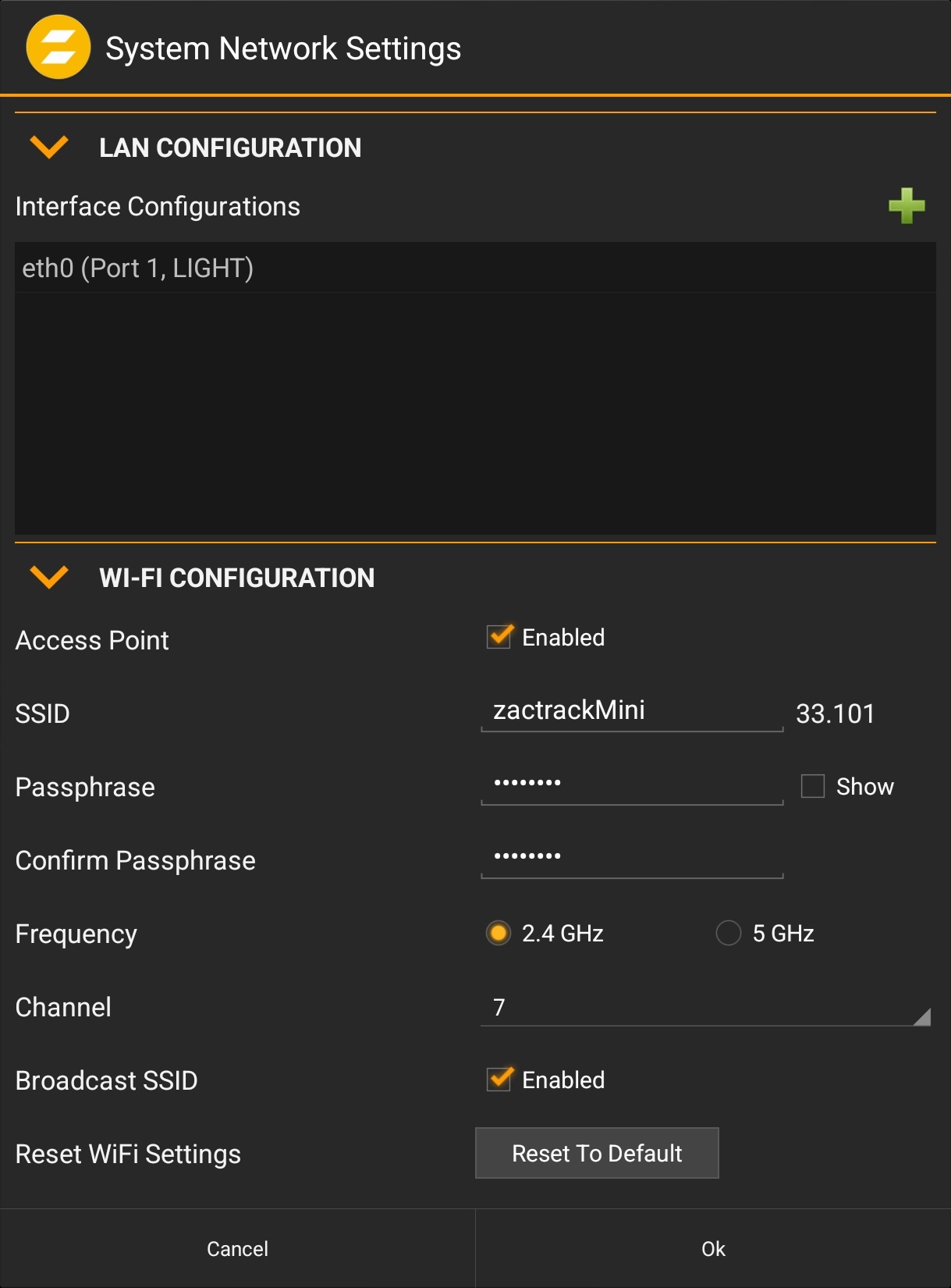
Change the Wi-Fi settings (optional)
Upon successful connection to the Server, the app will show a warning that the default Wi-Fi password is in use, which imposes a security risk.
 |
Click the warning banner.
Alternatively, tap the
 icon in the top right to open the system menu, select , tap the button and select
 In the dialog, change the passphrase and adapt the rest of the parameters if desired.
Tap the button to store the changes.
Confirm the changes in the dialog by tapping the button.
 |
Tip
The Wi-Fi settings can be restored to the default (as printed on the label on the backside of the Server) by tapping the button.
Create a new Show
Tap the
icon in the top right to open the system menu.Select .
In the dialog, select and tap .
Confirm the warning dialog to create the empty Show.
Note
The showfile is created and edited on the app and needs to be uploaded to the server in order for the changes to take effect. The server operates with the current showfile until a new one is uploaded. The app allows working on a showfile (including import and export) without requiring the presence of a server.
System settings are stored independently from the show history. Hence, creating a new show does not change these settings.
Set the Show Details
Tap the
icon in the top right to open the system menu.Select .
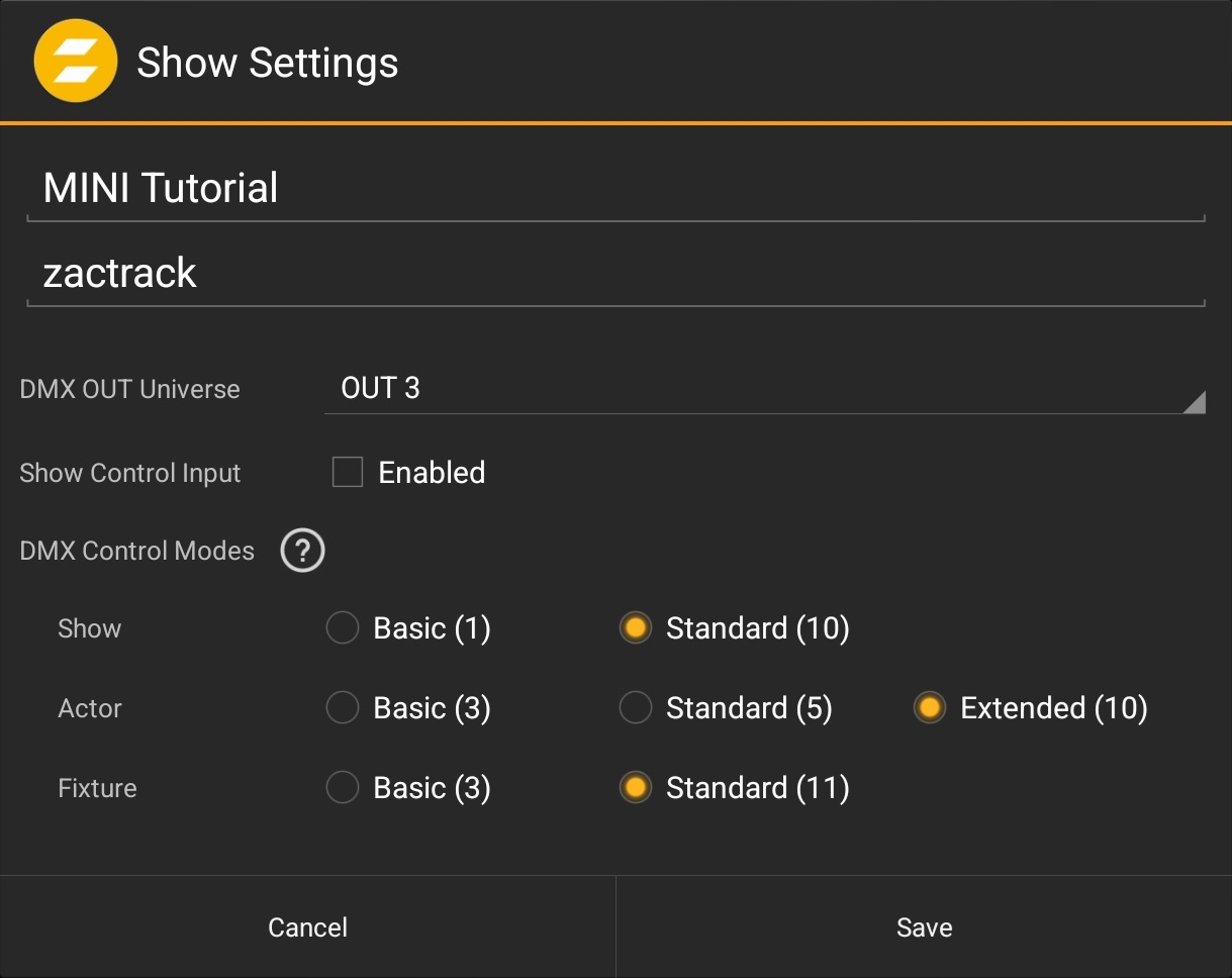
In the dialog, provide a name and author (optional) for the show. These settings can be changed later at any time. DMX settings can be left unchanged at this point of time. They will become relevant in the Integrate step later.
Confirm the changes by tapping the button.
 |
Tip
The name field can also be used to add useful short notes about the changes made in a particular showfile version, e.g. added fixtures or changes made to autofunctions.
Upload to the Server
Tap the sync button in the top right next to the Server connection indicator.
In the dialog, select .
The showfile has been uploaded and the sync button will change its icon to
 .
.
Note
The Server keeps a history of previously uploaded showfiles, each indicated by a version number.
The sync state to the server is indicated by different icons:
The local (in-app) showfile is fully synced and running on the Server.
 The local showfile has changes, which are not yet uploaded to the Server.
 The Server has a different version (e.g. a higher version number) than the local showfile. This can be the case e.g. when the tablet contains a showfile from another system/production.
Add Anchors
Switch to the via the top navigation bar.
Select the tab via the bottom navigation bar.
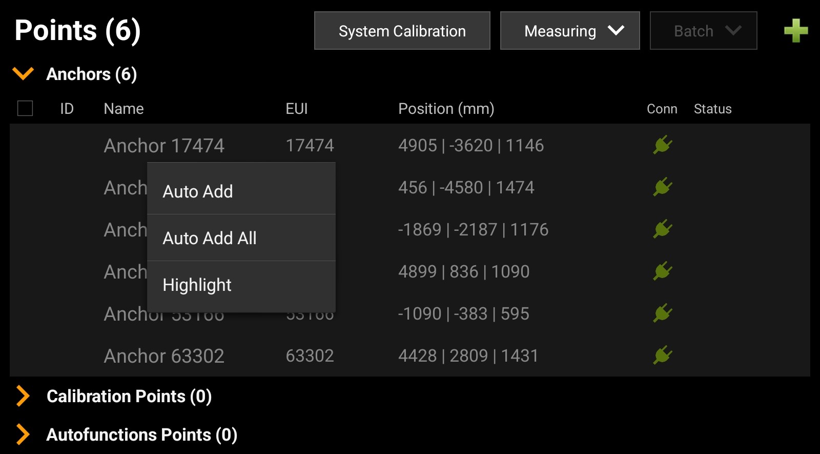
All Anchors will show up in the list as grey items. To add all Anchors to the Show at once, long-tap on one of the items.
Select to automatically add all Anchors to the Show.
Upload the Show to the Server.
 |
Tip
Anchors can also be added individually by tapping each grey entry and confirm the settings in the dialog.
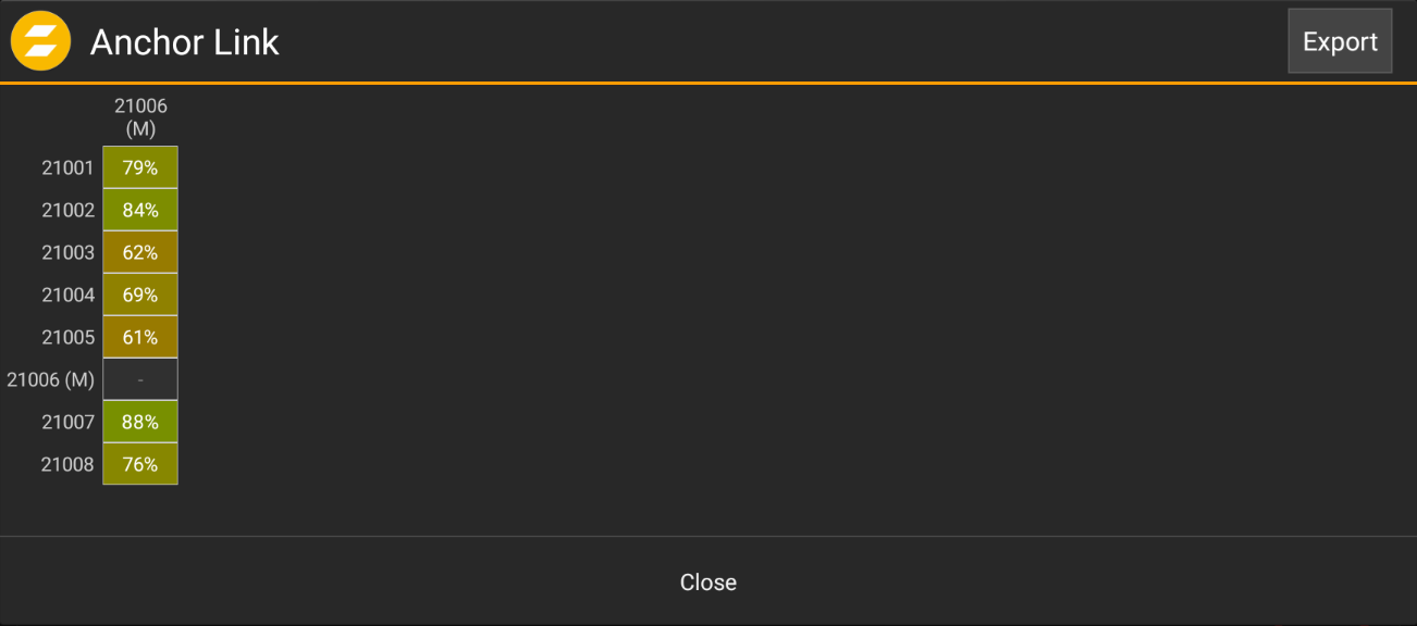
Check the Anchor Link
Once all Anchors are added to the Show, the system will start the wireless communication of the Anchors. zactrack MINI requires a stable UWB connection between all Anchors and the Master Anchor. The connection quality can be checked in the Tracking Settings.
Tap the
icon in the top right to open the system menu.Select .
In the dialog, tap the button.
The Anchor Link dialog is shown, presenting a realtime status of the connection quality between the Anchors and the Master Anchor.
 |
Note
A stable connection is characterized by numbers of 85% or higher, indicated by a green cell background.
If individual Anchors are showing low numbers, optimized their location by either repositioning them or removing obstacles.
If low numbers are shown across the entire list, the system is operating at its limits in terms of range (area size). Raising the power offset can resolve this issue. Tap the
icon and go to the . Slowly raise the Transmission Power Offset in the General Settings section while monitoring the changes in the Anchor Link until the quality indices improve.
Add Trackers
Take out all Trackers from the Charging Bay or disconnect the USB-C power. This will bring all Trackers online.
Switch to the via the top navigation bar.
Select the tab via the bottom navigation bar.
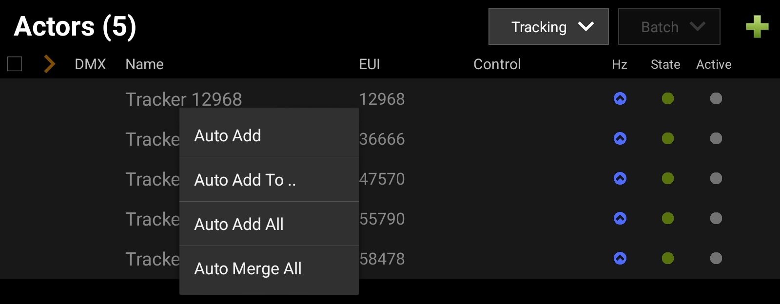
All Trackers will show up in the list as grey items. To add all Trackers to the Show at once, long-tap on one of the items.
Alternatively, each entry can be tapped and added individually.
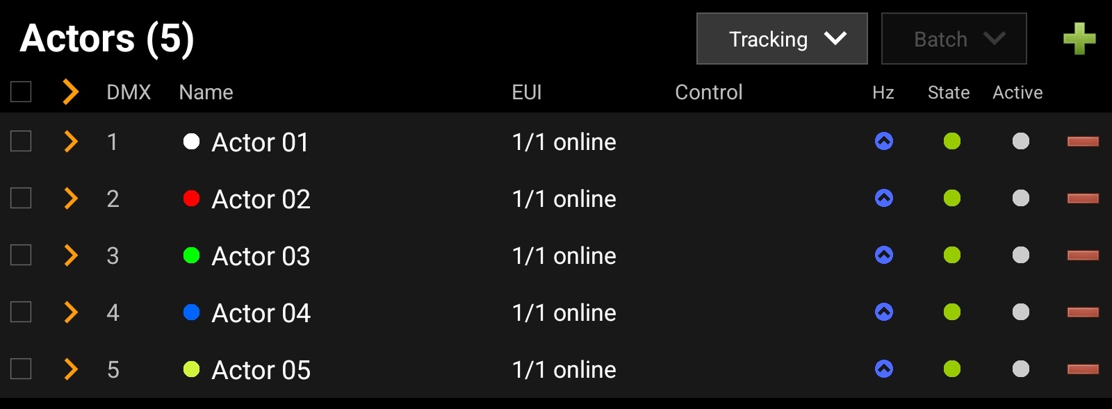
Select to automatically add all Trackers to the Show. Each Tracker will be assigned to a new Actor.
Upload the Show to the Server.
 |
After uploading the show, the server will provide status information for the Trackers assigned to each Actor.
 |
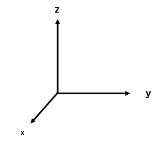
Define the Coordinate System
The tracking system needs a defined coordinate system in order to create a relation between the physical space and computed tracking positions. This is done by defining an origin and 3 axes (X, Y, Z). Since the coordinate system's axes are orthogonal to each other, it is sufficient to clearly define the origin and the x-axis. The y-axis just needs a definition of its principal direction to the "left" or "right" of the x-axis. The z-axis consequently is defined being orthogonal to the other axis, pointing upwards.
 |
Placing 4 Trackers on the floor - each with a specific role - fully defines a coordinate system for the tracking computations.
Tracker | Disk | Role |
|---|---|---|
1 | White | Origin |
2 | Red | X-Axis |
3 | Green | Y-Axis (principal direction) |
4 | Blue | Auxiliary measurement point |
Before starting the calibration procedure, it is necessary to define which Trackers shall take which role for the coordinate system definition.
Note
These settings only need to be done when changes are needed. Once configured, the system will always assign each Tracker with its defined role.
Tap the
icon in the top right to open the system menu and select Go to the Calibration Settings section and define which Tracker shall take which role using its EUI. The number can be edited manually or selected in a dialog by tapping the button.
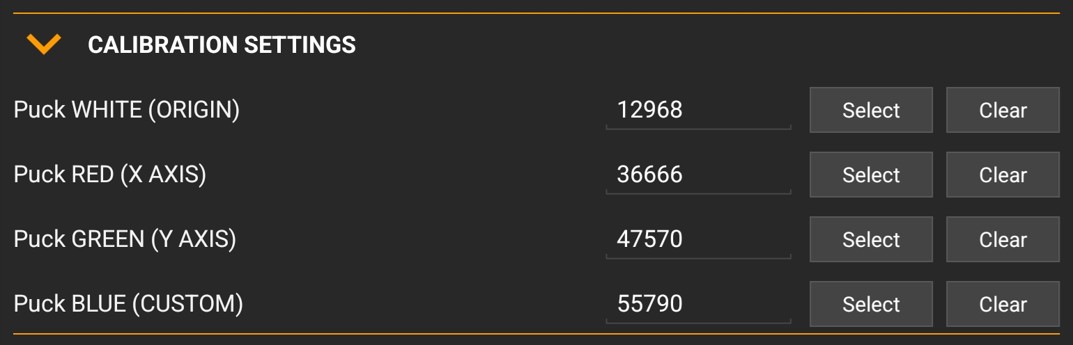
Confirm the settings and close the dialog by tapping the button.
When the roles are defined, the Trackers can be placed on the tracking area. Place the Trackers with a distance of at least 3m apart from each other. For larger tracking areas, this can be increased accordingly.
Calibrating the Tracking System
After all preparations have been done, the Trackers are placed on the tracking area for performing the calibration.
In the tablet app, switch to the and open the tab.
Tap the button, which opens the calibration wizard.
Select in order to perform a new calibration and tap the button.
All existing anchors will be listed and are pre-selected for the calibration. Confirm by tapping the button.
In the next dialog view, observe that 4 of 4 pucks (the Trackers in the colored disks) are online. If other Trackers shall be chosen, enable the switch and select different Trackers.
Tip
If the tracking area is not a flat surface, the advanced mode also allows defining z-heights for the individual tracker positions, e.g. when being placed on a stage riser.
Tap the button.
The wizard guides through the placement procedure by displaying a visualization. The individual steps can be seen by using the arrow buttons on the left and right side. The Trackers need to be placed on the tracking area. Take Trackers 1-4 out of the Charging Bay and place them into the colored disks according to their role. They will also blink in accordance to the role's color.
The wizard guides through the placement procedure by displaying a visualization. The individual steps can be seen by using the arrow buttons on the left and right side.
Tap the button. The system is performing the calibration (called "mesh ranging"), which takes approximately 1-2 minutes. To ensure the best possible calibration, the area should be free of people or objects being moved.
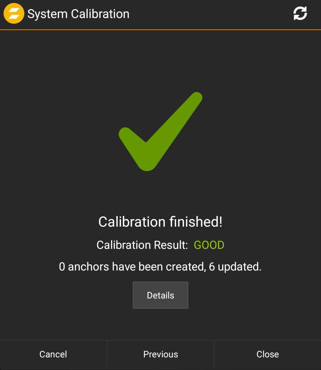
When the calibration is finished, the wizard will display the result. Finish the calibration process by tapping the button.
Upload the Show to the Server and put the trackers back into the charging bay.
Note
Tap the button to check possible issues in case of a failed or insufficient calibration result. The calibration quality can be affected in case of bad radio reception, anchors or trackers being moved during the process or insufficient anchor placement.
Perform a tracking test
After a successful calibration, the system is ready for tracking.
In the tablet app, switch to the view.
Take one of the trackers out of the charging bay and walk across the tracking area. Observe the position of the associated Actor in the visualizer.
Place the tracker on the origin and walk along the x-axis or other positions in order to verify the correctness of the calibration.
Next: Integrate