PTZ Camera Integration
This article provides an introduction to PTZ camera control within the zactrack environment, focusing on supported control protocols and two fundamental control modes: absolute and relative positioning. It explains how each mode operates and highlights key differences in behavior and implementation. To illustrate these concepts, the article also presents two real-world examples for each control mode, using specific camera models to demonstrate how absolute and relative control are applied in practice.
As with pan/tilt lighting fixtures, integrating PTZ cameras into zactrack requires a fixture alignment to determine the device’s precise position and orientation.
Control Protocols
In PTZ camera control, NDI and VISCA represent two widely used but fundamentally different approaches to communication. NDI (Network Device Interface), is an IP-based protocol that transmits both video and control data over standard Ethernet networks, enabling low-latency control and integration within modern networked production environments. VISCA, originally developed by Sony, is a command-based protocol specifically designed for controlling PTZ functions such as pan, tilt, zoom, and presets. VISCA can operate over traditional serial connections (e.g., RS-232 or RS-422), where commands are sent directly over dedicated cables, or over IP networks (VISCA over IP), where the same command structure is encapsulated in network packets. VISCA control in zactrack is enabled using the IP-based variant.
Note
Before integration a new camera, ensure that the required control protocols (VISCA, NDI, FreeD) are enabled in the System Settings.
Control Modes
In PTZ camera systems, absolute and relative control modes differ in how movement commands are interpreted. Absolute control specifies a precise target position using fixed coordinates (for example, a specific pan angle and tilt angle), meaning the camera moves directly to that exact orientation regardless of its current position. This is also the standard control mode in the lighting world using DMX.
In contrast, relative control issues movement commands based on the camera’s current position, such as “move to the right with 50% speed”, “tilt up with speed 100%” or "stop," so the final position depends on where the camera starts.
In relative control mode, effective positioning relies on continuous feedback from the camera about its current pan and tilt angles. This functionality is implemented via the FreeD protocol. Because commands are issued as incremental movements rather than fixed destinations, the control system must monitor the camera’s real-time position to determine when the desired offset has been achieved. This feedback loop allows the controller to calculate the remaining distance to the target and issue a stop command at the appropriate moment, preventing overshoot or drift. Without accurate and timely position reporting, relative control would lack precision, as the system would have no reliable way to know when the intended movement has been completed.
Video Streaming
NDI is widely used to stream high-quality, low-latency video over standard IP networks. By transmitting video and metadata in real time, it enables zactrack to easily access live camera feeds without dedicated video cabling. This allows the system to receive the camera’s video stream directly over the network and use it for alignment, ensuring accurate setup. However, this is an optional step and not strictly required for operation. The camera alignment can also be performed using an external video monitor (ideally with crosshairs), providing a simple alternative that does not rely on network-based video streaming to the zactrack server.
Some camera models, e.g. the Sony BRC-H800, do not support video streaming. For this, a separate NDI source can be assigned to the Fixture (e.g. a HDMI-NDI converter) in order to stream the converted videofeed to the server.
Tip
Use the NDI Tools - specifically the Studio Monitor - on a PC in the camera network to access NDI video streams and discover cameras in the network. The app also provides a link to the camera's web interface.
Note
Make sure to use the latest camera firmware. Some models require a separate license for unlocking NDI functionality.
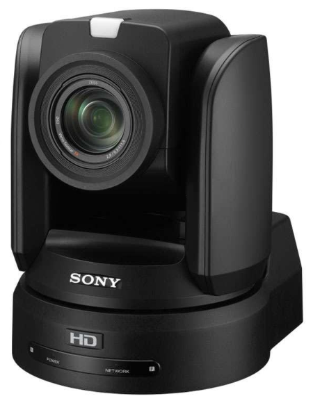
Sony BRC-H800 (Absolute)
The Sony BRC-H800 supports control via VISCA over IP and works best with the absolute control mode.
 |
Adding the camera to the Showfile
Connect the camera to the zactrack network (Ethernet port on MINI, LIGHT interface on SMART/PRO or one of the two additional interfaces on PRO).
Access the camera's web interface with a web browser and check the network settings. Check the BRC-H800 User Manual for more details.
On zactrack side, access the System Settings, go to the Network Settings and set or add a compatible IP for the respective network interface. A common configuration is to use the 192.168.0.x/24 network.
In the Show Editor, switch to the tab and tap the
 button.
In the Fixture Library dialog, switch to the tab and select from the list of cameras.
Adjust the Fixture Type name as needed and tap . The Fixture Type dialog will be shown. Leave the settings unchanged and tap to create the Fixture Type.
Switch to the tab and tap the
button.In the dialog, select the previously created camera Fixture Type and confirm by tapping .
Optionally, define a control input for remotely controlling the camera's zactrack-related functions.
The Fixture detail dialog is shown. Set the Camera IP and the VISCA Port according to the settings made on the camera itself.
Optional step: If the camera's video stream is converted to an NDI stream, define the NDI Video IP and choose the NDI Video Channel by tapping the button and choosing a source in the dialog.
Note
It is not strictly required to receive the video stream in the zactrack server, but improves the Fixture focus handling during the Alignment process by showing the camera frame in the dialog. Alternatively, the video stream can be shown on an external monitor, ideally with a crosshairs.
Leave the remaining settings unchanged and confirm by tapping .
Upload the Showfile.
Camera Alignment
The alignment process is the same as with lighting fixtures. The camera needs to be focused on 4 or more known points. Since the focus point (frame center) is directly visible in the video feed, the alignment can be done "pixel-accurate" without the requirement of sensors on the target, as it is the case with the pucks.
When performing the alignment (using the Alignment Wizard or via the CP/AF dialog) place the Pucks on the tracking area as usual. Make sure to distribute them so that both the pan and tilt movement of the camera between the points is maximized. The same rule applies to fixed calibration points as targets.
Use the Zoom slider to zoom the frame in order to precisely focus on the target.
Tip
When the camera is mounted mid-level and targeting the tracking area mostly horizontally, it might be necessary to have at least one alignment point with an elevated z-position in order to increase the tilt spread between the points.
Camera Zoom
The camera zoom can be controlled from zactrack via the Zoom slider from the Autofunctions panel. However, the BRC-H800 only accepts a limited amount of control commands at a given time. Since Pan/Tilt commands need to have higher priority for reliable tracking, zoom command are only issued approx. once per second.
Tracking Operation
Controlling the camera's zactrack function works the same way as with lighting fixtures, algthough some functions are not available for this type of device, e.g. Crossfade or Fixture mode. Assignment, Transition time and the offset can be controlled by the App, Web Monitor or remotely via DMX or OSC. The Live dialog also provides a button to view the NDI Video Stream (if present).
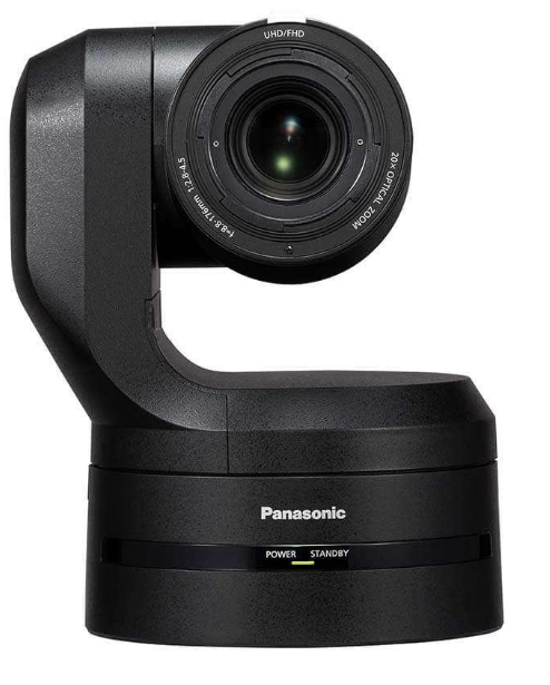
Panasonic AW-UE150 (Relative)
The Panasonic AW-UE150 supports control via NDI and works best with the relative control mode.
 |
Adding the camera to the Showfile
Connect the camera to the zactrack network (Ethernet port on MINI, LIGHT interface on SMART/PRO or one of the two additional interfaces on PRO).
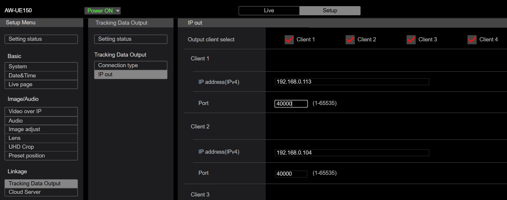
Access the camera's web interface with a web browser and check the network settings. Check the AW-UE150 User Manual for more details. Since this camera is working in relative mode, it needs to send back its pan/tilt position to the zactrack server. Switch to the Tracking Data Output, choose one of the 4 possible destinations, enter the zactrack server IP and activate it.
On zactrack side, access the System Settings, go to the Network Settings and set or add a compatible IP for the respective network interface. A common configuration is to use the 192.168.0.x/24 network.
In the Show Editor, switch to the tab and tap the
button.In the Fixture Library dialog, switch to the tab and select from the list of cameras.
Adjust the Fixture Type name as needed and tap . The Fixture Type dialog will be shown. Leave the settings unchanged and tap to create the Fixture Type.
Switch to the tab and tap the
button.In the dialog, select the previously created camera Fixture Type and confirm by tapping .
Optionally, define a control input for remotely controlling the camera's zactrack-related functions.
The Fixture detail dialog is shown. Set the Camera IP according to the settings made on the camera itself. This camera can directly stream video via NDI using the same IP address. Choose the NDI Video Channel by tapping the button and choosing a source in the dialog.
Note
It is not strictly required to receive the video stream in the zactrack server, but improves the Fixture focus handling during the Alignment process by showing the camera frame in the dialog. Alternatively, the video stream can be shown on an external monitor, ideally with a crosshairs.
Ensure that the FreeD port number is the same as configured on the camera itself. (Port number in the Tracking Data Output) Leave the rest of the settings unchanged and confirm by tapping .
Upload the Showfile.
Tip
The camera should already report its pan/tilt position to zactrack. Incoming data can be observed in the Analyzer Tab.
For relative motion control, the system needs to know the camera's exact pan/tilt limits. Open the Fixture dialog again and tap the button. This will start a calibration routine that moves the cameras to its pan/tilt limits and reads out the respective values reported back from the camera.
Once done, confirm with and close the dialog.
Upload the Showfile.
Camera Alignment
The alignment process is the same as with lighting fixtures. The camera needs to be focused on 4 or more known points. Since the focus point (frame center) is directly visible in the video feed, the alignment can be done "pixel-accurate" without the requirement of sensors on the target, as it is the case with the pucks.
When performing the alignment (using the Alignment Wizard or via the CP/AF dialog) place the Pucks on the tracking area as usual. Make sure to distribute them so that both the pan and tilt movement of the camera between the points is maximized. The same rule applies to fixed calibration points as targets.
Use the Zoom slider to zoom the frame in order to precisely focus on the target.
Tip
When the camera is mounted mid-level and targeting the tracking area mostly horizontally, it might be necessary to have at least one alignment point with an elevated z-position in order to increase the tilt spread between the points.
Tracking Operation
Controlling the camera's zactrack function works the same way as with lighting fixtures, algthough some functions are not available for this type of device, e.g. Crossfade or Fixture mode. Assignment, Transition time and the offset can be controlled by the App, Web Monitor or remotely via DMX or OSC. The Live dialog also provides a button to view the NDI Video Stream (if present).
Motor Control Parameters
For controlling pan/tilt in the relative mode, the system needs to constantly adjust the motor direction and speed according to the target position and the camera's current position. The related speed curve per movement axis is defined by multiple parameters:
Min Limit: Starting point from which the motor control sends a direction command with minimum speed. When the difference between the camera's reported position and the target position is below this limit, a stop command is sent. A lower value will increase the (theoretical) accuracy, but may lead to overswinging if set too low.
Max Limit: Point from which the maximum speed is issued. A lower value will bring the camera up to speed earlier, but may result in lower motion smoothness.
Max Speed: Percentage of the camera's maximum speed capability. A lower value makes the camera motion smoother, but also decrease reactivity.
Falloff: Shape of the curve interpolating from the lowest to the highest speed. A value 1 results in a linear speed increrase/decrease.
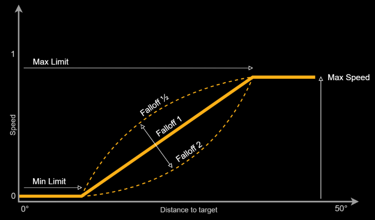 |
The relative motion curve is a parameter on the Fixture Type and set to a default value when creating a new Type. The curve can be manually adjusted by activating the gu option. Auto-adjustment can be performed by tapping the button and following the instructions.