Points
The area points include
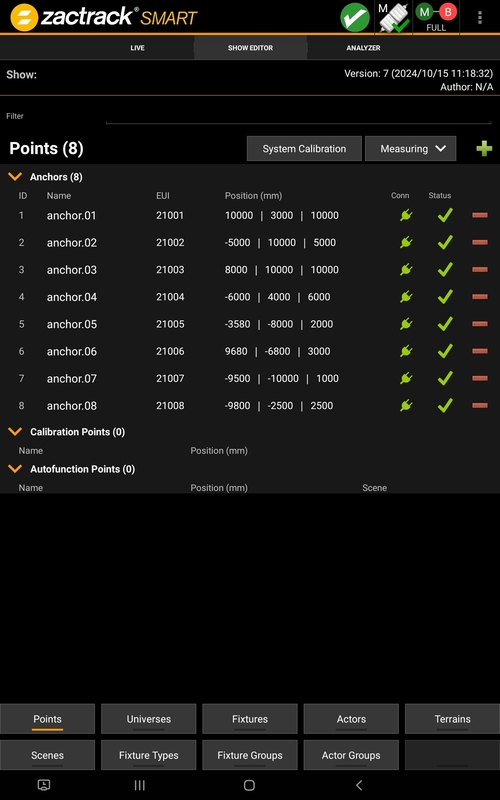
Anchors
An Anchor is the radio receiver of the tracking system. In this menu it is possible to add or remove anchors, give them coordinates and see status information.
Calibration Points
A calibration point is a point in the absolute coordinate system. It is possible to use it for an alignment, or e.g. a coordinate transformation for the OSC coordinate system.
Autofunction Points
An Autofunction Point is an absolute coordinate point with a stored Dimmer value, for instance. Autofunctions can be added with the Autofunction App or the Autofunction Wizard.
Coordinate System
The definition of the coordinate system is done in the menu points.
 |
Press Measuring for more options.
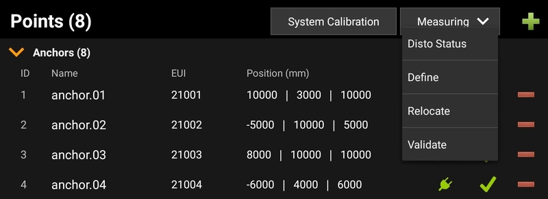 |
Using this wizard, different options for the system setup and a system check are available.
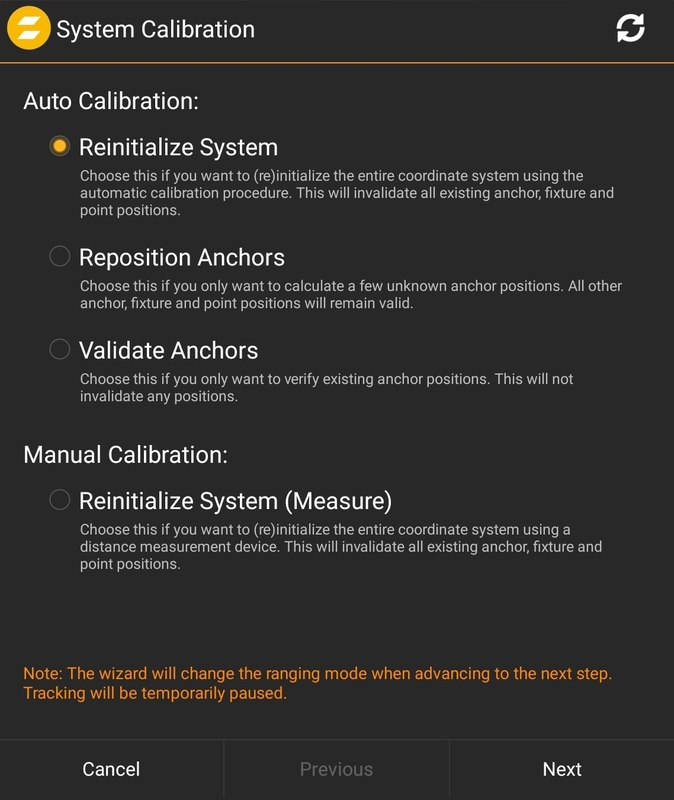 |
This wizard will create a coordinate system and all positions of the Anchors with a mesh ranging procedure, based on the Puck Position. See Measure for more Details.
In case of only changing single pieces in the system it is possible to reposition an Anchor.
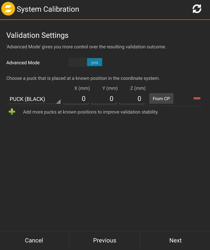
This powerful tool uses the mesh ranging process to check all Anchor positions. With adding a single Puck position it is also possible to get information of a shift to the coordinate system.
Set one Puck at a known point. this could be a coordinate or also a calibration point.
 |
After Pressing next, the system performs a mesh ranging process. this could take some minutes. The result shows as a green check or an orange sign.
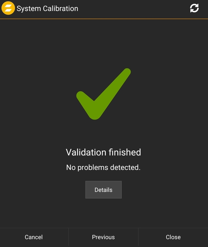 |
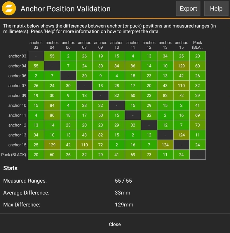
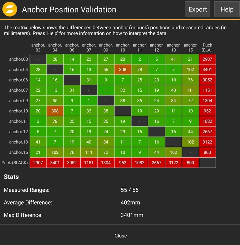
By clicking the Details button a complete ranging matrix with all results will be shown.
 |
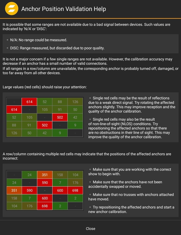
Clicking Help will open a short description to understand how problems with one ore more wrong anchors is detectable. In the picture above, no issue is detected.
 |
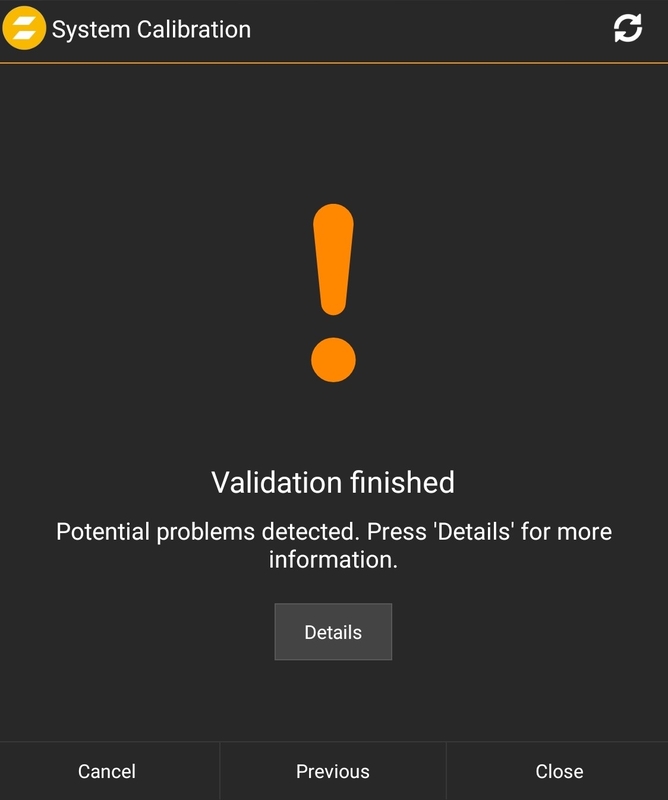
The system will automatically detect an issue and message a potential problem.
 |
The picture below shows a wrongly placed puck. If the puck is on the correct position it is possible that all anchors (maybe on a rig) are shifted. Wrong z height for example.
 |
The next picture identifies two incorrectly placed Anchors.
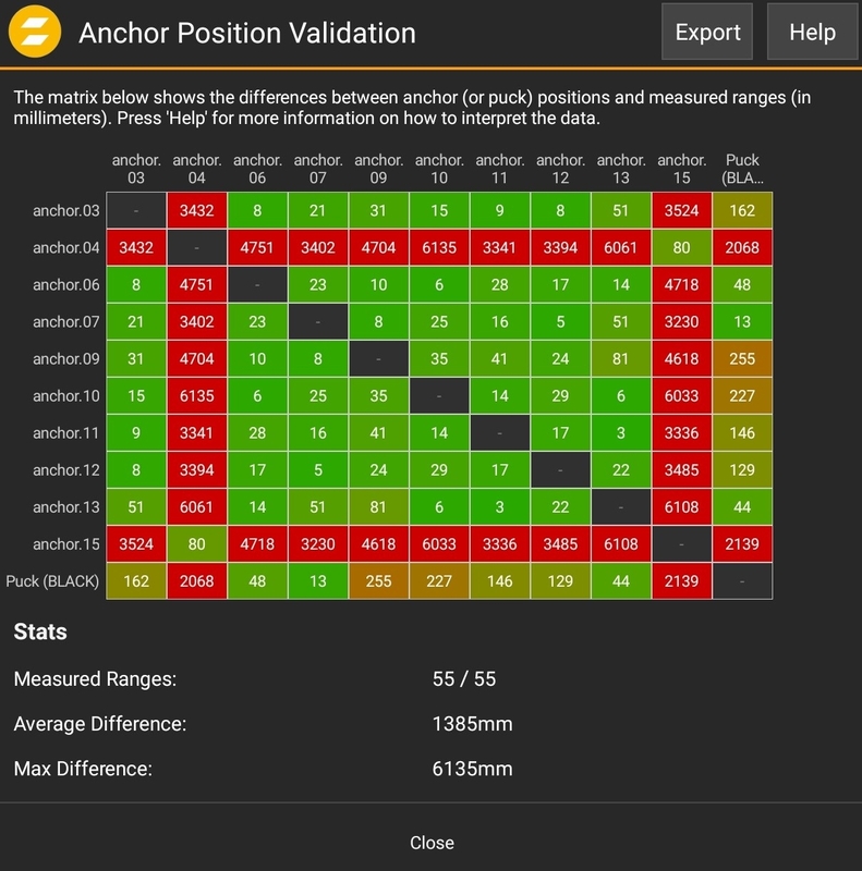 |
This wizard will guide through a manual calibration process with the Leica.
It is possible to add manual points. Just click the  symbol.
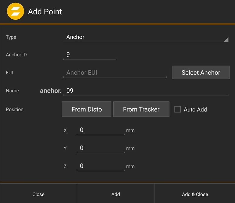 |
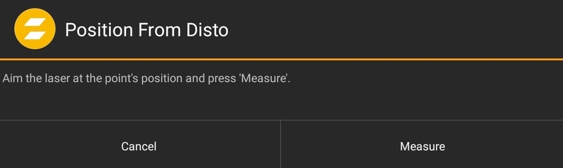
It is possible to add an Anchor or a Calibration Point. Just enter the absolute coordinates in the XYZ line, or use the position from a tracker or from the measurement tool Disto.
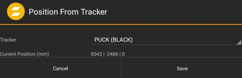 |
 |
Note
Adding a position from a Tracker needs a calibrated system!
Tip
Connect Anchors to the system first. All connected Anchors will show up in light grey color in the Anchor List. Add them with a long press.
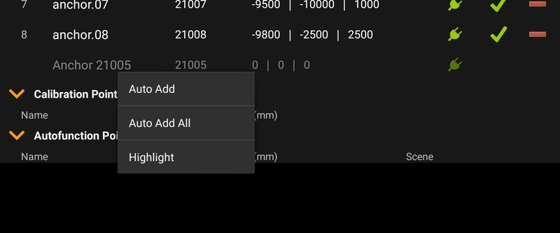 |
Tip
A long press on an Anchor can highlight it (Front LED Flashing), this can be used for identifying an Anchor.
In case of a fixed installation or a situation where the Auto System Calibration is not working. It is possible to manually measure the system. For that purpose, zactrack supports Disto Leica. Supported Devices:
Disto S910 (Wi-Fi)
Disto X3 (BT)
Disto X4 (BT)
Disto X6 (BT)
To avoid typos, there is a direct connection between the Disto device and the Tablet. The old generation uses WIFI, the new Generation uses Bluetooth.
Wi-Fi Connection
Normal Mode: Make sure that the Android device and the Disto device are connected to the same Wi-Fi network.
Hotspot Mode: Connect the Android device to the hotspot of the Disto S910 Device.
Bluetooth Connection
Make sure that the zactrack application has permission to use Location and Bluetooth
Make sure that Location and Bluetooth is turned on
The Bluetooth Discovery is done in the zactrack App
It may take up to a minute to connect
To use the virtual keyboard while the Disto device is connected, it is necessary to disable the "Text Input" option in the Bluetooth settings of the Android device.
Warning
Some Tablets use the new Bluetooth connection as the keyboard. It is necessary to deactivate it in the settings of the Android device.
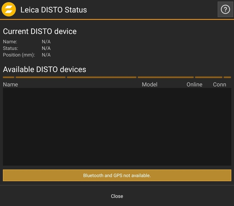 |
No connected device, Bluetooth and GPS not availible.
Tip
Activate Bluetooth and GPS and allow the zactrack App to use it.
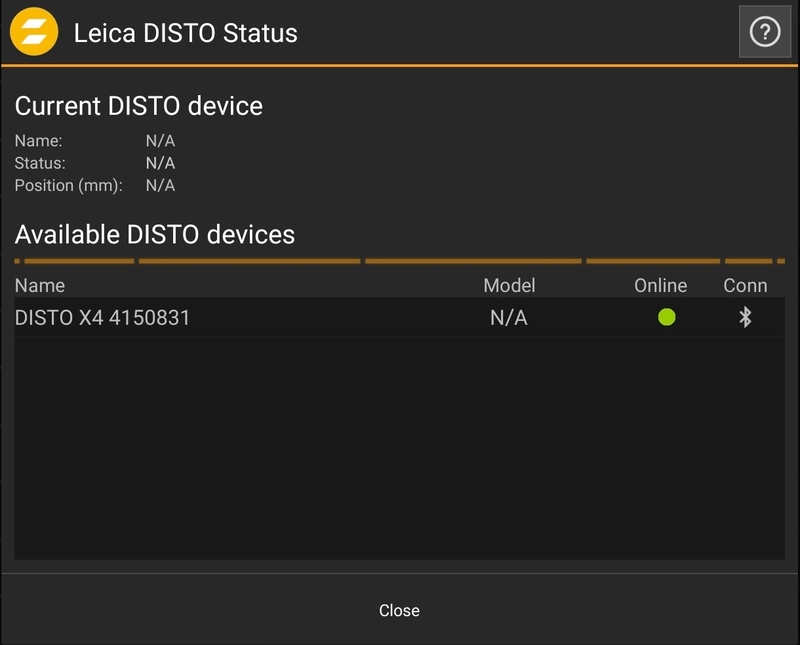 |
Discovered Bluetooth Device. Press on the Bluetooth symbol to initialize a connection.
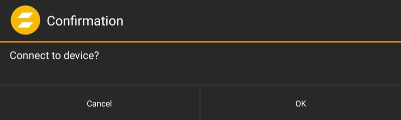 |
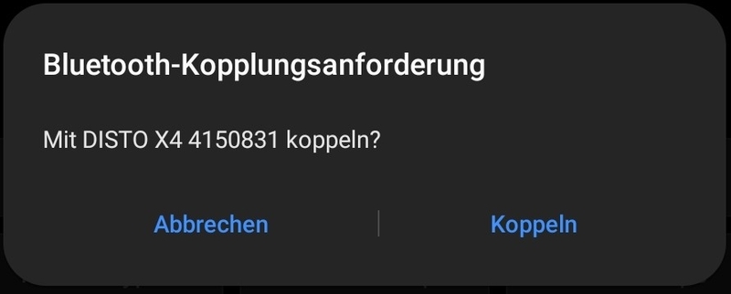
Maybe the Android system is asking for permission. Press yes or OK.
 |
If everything worked, the connection is established.
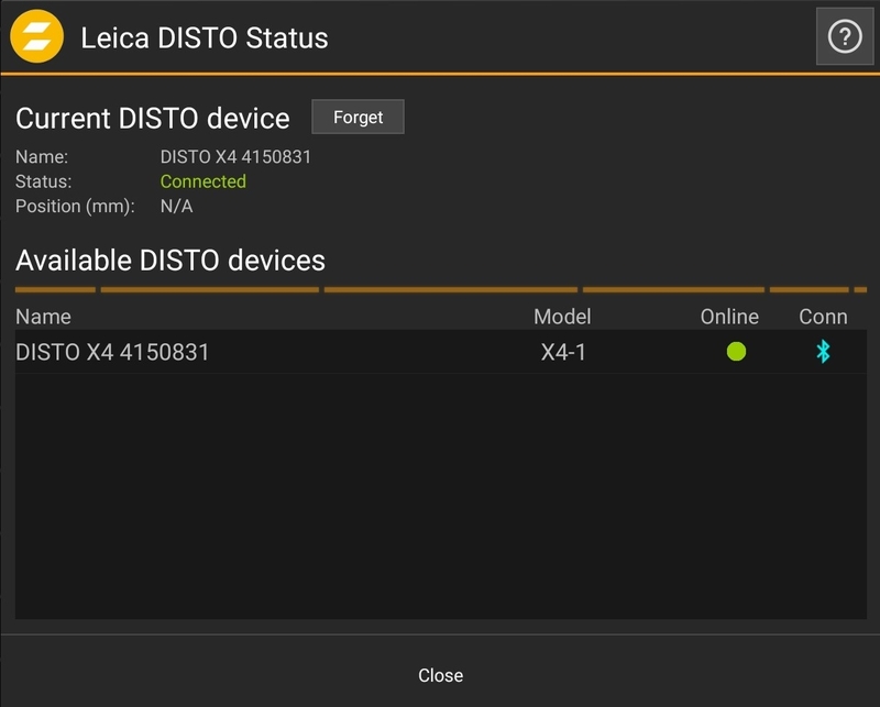 |
Tip
If the Disto is used with different tablets, use the Forget button to be able to connect with other devices.
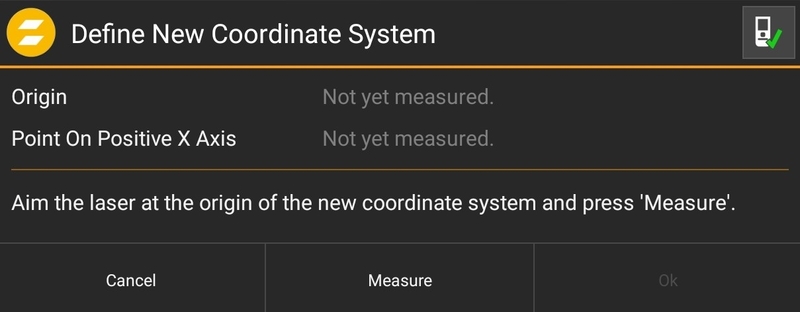
Press Define in the Measuring drop down menu to manually set up a new Coordinate System. This step is automatically done in the Calibration Wizard.
 |
Warning
It is possible to keep all old points, make sure these points are not related to the new coordinate system.
A coordinate system only needs two points to be defined.
Origin
Point on the X Axis
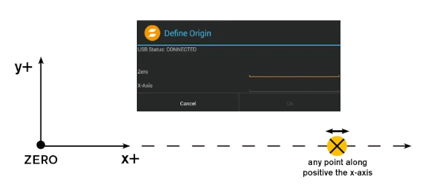 |
The Rest of the coordinate system is automatically handled with the right hand rule.
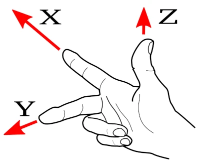 |
The Relocate option allows the movement of the measurement device to a different place. After moving the device this function will calculate the position based on the coordinate system.
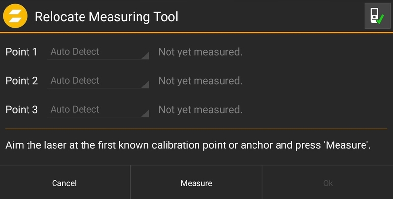 |
Just measure 3 different existing points. These could be Anchors or Calibration points.
Tip
To get a good Relocate position, try to use points in different positions. For best results there should be a big difference in the XYZ coordinates.
Warning
Moving the measuring tool without choosing Relocate will cause wrong positions for Anchors and Calibration points.
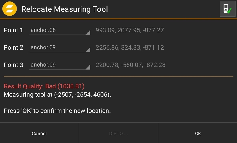 |
The tool automatically detects the points. In case of a bad result it is possible to use the right points manually.
The last point is there to validate the position of the measuring tool in order to check if something has moved the tool.
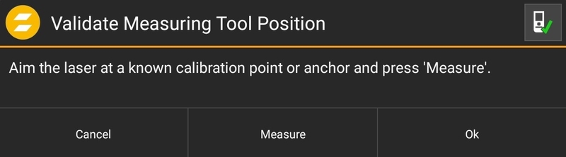 |